A. Background:
Lead (Pb) containing solders are being replaced by lead-free
solders because of environmental concerns. In addition to
environmental problems, the technical limits of tin-lead solders,
in particular its
relatively low-strength, are
currently being reached as component operating temperatures are
increasing and finer pitch components with smaller solder joints
are becoming the industry standard. The manufacturers
have to change fast over to
the lead-free alternatives because of legislation and laws being
introduced to check the use of lead based materials in
electronics industry. But, there is not much detail available on
the
thermo-mechanical behaviour
of various lead-free solder alloys with respect to different
components and finishes on PCB. The manufacturers also want to
have a rapid test method to compare the joint reliability.
This project proposes to
develop a rapid reliability test method for comparing solder
joints with different alloys and components.
B. Proposed
Research: To date, a large proportion of the work
undertaken on lead free solders has concentrated on chemical
composition of alternative solder alloys and their compatibility
with different sets of PCB
finishes. Manufacturing
related issues are also being reported. But there is little, if
any, work reported on the mechanical reliability and strength of
lead free joints. Currently in NMRC work has been going on to
develop a means of measuring
the mechanical behaviour of a range of lead-free solder materials
through the design and test of specimens, which reflect real
joint behaviour. Usually the reliability tests take too long
and sometimes can go as long
as six months. Some rapid testing has been reported for
lead-based solder joints but currently there is no available
rapid test method that allows judging the reliability of solder
joints.
Therefore the objectives of this project are:
The novel aspects of this project will be:
The work plan for this project is to start with the review of
literature of lead-free solder development and new rapid testing
methods. This will go alongside in getting acquaintance and
experience with
various processes and equipments to be used for this project.
This include the assembly process of the PCB, using mechanical
testers (INSTRON and DAGE) and various reliability test processes
like
thermal vibration, thermal cycling tests, etc. After this stage,
the reliability testing of conventional lead-based solder joints
will start. This will go alongside with finding new techniques
for rapid testing of
these joints. This includes the combined heat and vibration
testing and the behaviour of yield strength of solder joints with
respect to temperature. Next, the numerical modelling will
commence as well as the
systematic study and comparison of various lead-free alloys and
components. The above description is presented in the form of bar
chart in the page attached.
The end result of this project will be to develop a rapid
reliability test method for the solder joints. It will also
provide a database of results on the reliability of lead-free
solders. The numerical model
developed in this project will also provide a reliability
prediction methodology strongly based on measured data.
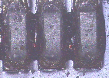
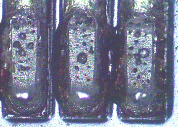
The above images show the solder pads after the leads have been
pulled of. Voids on the pads can be seen very clearly.
Developments
The project has changed a lot since its inception. The pull test and shear tests are no longer a part of the project as they are unable to replicate the same failure mode and mechanisms in thermal cycling test, which is the most common reliability test for solder joint.
The three tests that have been selected are :
Animations showin cyclic displacement, bending and twisting test respectively.
These tests are able to induce plastic strains in the joints in the same way as thermal cycling. However, since the effect of CTE mismatch is not included in mechanical cycling, the failure mechanisms are not same. In thermal cycling failure the most common failure mechanism is inter-granular in nature, associated with low cyclic strains and accompanied with grain boundary sliding. In mechanical cycling, due to higher stresses, the failure mechanism in trans-granular in nature. Efforts are curently underway to combine thermal and mechanical cycling, in order to get the required failure mechanism. Initial results, both on QFP and BGA, are promising.
FEA/FEM simulation
This project involves lot of simulation work as well. Simulation of thermal cyclingon QFP and BGA has been caried out in order to save time taken in experimentation. The simulation includes transient and non-linear behaviour of solder joints (In ANSYS Anand's model has been used). By calculating Plastic work energy, number of cycles to crack initiation and crack propagation rate during thermal cycling has been calculated. Fig. 6 shows the plastic work energy in Gull-wing lead during one cycle of thermal cycling. The figure clearly shows the crack growth path in the joint.

Fig. 6 Plastic Work energy in QFP solder Joint
This page was last updated on 8th Feb. 2001.
Copyright: Yasir A. Quadir, UCC, NMRC